High-frequency communication (≥MHz)
High frequency communication may (re)use large portions of the radio spectrum for communication, or may use select (narrow) band(s), depending on the technology.
Home networking (broadband)
Power line communications can also be used to interconnect home computers, peripherals or other networked consumer peripherals, although there is not yet a universal standard for this type of application. Standards for power line home networking have been developed by a number of different companies within the framework of the HomePlug Powerline Alliance and the Universal Powerline Association.
Internet access (broadband over powerlines
Broadband over power lines (BPL), also known as power-line Internet or powerband, is the use of PLC echnology to provide broadband Internet access through ordinary power lines. A computer (or any other device) would need only to plug a BPL "modem" into any outlet in an equipped building to have high-speed Internet access.
BPL may offer benefits over regular cable or DSL connections: the extensive infrastructure already available appears to allow people in remote locations to access the Internet with relatively little equipment investment by the utility. Also, such ubiquitous availability would make it much easier for other electronics, such as televisions or sound systems, to hook up.
But variations in the physical characteristics of the electricity network and the current lack of IEEE[1] standards mean that provisioning of the service is far from being a standard, repeatable process. And, the amount of bandwidth a BPL system can provide compared to cable and wireless is in question. The prospect of BPL could motivate DSL and cable operators to more quickly serve rural communities.
PLC modems transmit in medium and high frequency (1.6 to 80 MHz electric carrier). The asymmetric speed in the modem is generally from 256 kbit/s to 2.7 Mbit/s. In the repeater situated in the meter room the speed is up to 45 Mbit/s and can be connected to 256 PLC modems. In the medium voltage stations, the speed from the head ends to the Internet is up to 135 Mbit/s. To connect to the Internet, utilities can use optical fiber backbone or wireless link.
The system has a number of issues. The primary one is that power lines are inherently a very noisy environment. Every time a device turns on or off, it introduces a pop or click into the line. Energy-saving devices often introduce noisy harmonics into the line. The system must be designed to deal with these natural signaling disruptions and work around them.
Broadband over power lines has developed faster in Europe than in the United States due to a historical difference in power system design philosophies. Power distribution uses step-down transformers to reduce the voltage for use by customers. But BPL signals cannot readily pass through transformers, as their high inductance makes them act as low-pass filters, blocking high-frequency signals. So, repeaters must be attached to the transformers. In the U.S., it is common for a small transformer hung from a utility pole to service a single house or a small number of houses. In Europe, it is more common for a somewhat larger transformer to service 10 or 100 houses. For delivering power to customers, this difference in design makes little difference for power distribution. But for delivering BPL over the power grid in a typical U.S. city requires an order of magnitude more repeaters than in a comparable European city. On the other hand, since bandwidth to the transformer is limited, this can increase the speed at which each household can connect, due to fewer people sharing the same line. One possible solution is to use BPL as the backhaul for wireless communications, for instance by hanging Wi-Fi access points or cellphone base stations on utility poles, thus allowing end-users within a certain range to connect with equipment they already have. In the near future, BPL may also be used as a backhaul for WiMAX networks.
The second major issue is signal strength and operating frequency. The system is expected to use frequencies of 10 to 30 MHz, which has been used for many decades by amateur radio operators, as well as international shortwave broadcasters and a variety of communications systems (military, aeronautical, etc.). Power lines are unshielded and will act as antennas for the signals they carry, and have the potential to interfere with shortwave radio communications. Modern BPL systems use OFDM modulation, which allows to mitigate interference with radio services by removing specific frequencies used. A 2001 joint study by the ARRL and HomePlug Powerline Alliance showed that for modems using this technique "in general that with moderate separation of the antenna from the structure containing the HomePlug signal that interference was barely perceptible" and interference only happened when the "antenna was physically close to the power lines".
Much faster transmissions using microwave frequencies transmitted via a surface wave propagation mechanism called E-Line have been demonstrated using only a single power line conductor. These systems have shown the potential for symmetric and full duplex communication well in excess of 1 Gbit/s in each direction. Multiple WiFi channels with simultaneous analog television in the 2.4 and 5.3 GHz unlicensed bands have been demonstrated operating over a single medium voltage line. And, because it can operate anywhere in the 100 MHz - 10 GHz region, this technology can completely avoid the interference issues associated with use of shared spectrum while offering flexibility for modulation and protocols of a microwave system.
Medium frequency (kHz)
Home control (narrowband)
Power line communications technology can use the household electrical power wiring as a transmission medium. INSTEON and X10 are the two most popular[unreliable source?], de factohome automation for remote control of lighting and appliances without installation of additional control wiring. standards using power line communications for home control. This is a technique used in
Typically home-control power line communication devices operate by modulating in a carrier wavekHz into the household wiring at the transmitter. The carrier is modulated by digital signals. Each receiver in the system has an address and can be individually commanded by the signals transmitted over the household wiring and decoded at the receiver. These devices may be either plugged into regular power outlets, or permanently wired in place. Since the carrier signal may propagate to nearby homes (or apartments) on the same distribution system, these control schemes have a "house address" that designates the owner. of between 20 and 200
Since 1999, a new power-line communication technology "universal powerline bus" has been developed, using pulse-position modulation (PPM). The physical layer method is a very different scheme than the modulated/demodulated RF techniques used by X-10. The promoters claim advantages in cost per node, and reliability.
Low-speed narrow-band communication
Narrowband power line communications began soon after electrical power supply became wide-spread. Around the year 1922 the first carrier frequency systems began to operate over high-tension lines with frequencies of 15 to 500 kHz for telemetry purposes, and this continues.[2][3] Consumer products such as baby alarms have been available at least since 1940.
In the 1930s, ripple carrier signalling was introduced on the medium (10-20 kV) and low voltage (240/415V) distribution systems. For many years the search continued for a cheap bi-directional technology suitable for applications such as remote meter reading. For example, the Tokyo Electric Power Co ran experiments in the 1970s which reported successful bi-directional operation with several hundred units.[4] Since the mid-1980s, there has been a surge of interest in using the potential of digital communications techniques and digital signal processing. The drive is to produce a reliable system which is cheap enough to be widely installed and able to compete cost effectively with wireless solutions. But the narrowband powerline communications channel presents many technical challenges. A mathematical channel model and a survey of work can be found in reference no. 5[5].
Applications of mains communications vary enormously, as would be expected of such a widely available medium. One natural application of narrow band power line communication is the control and telemetry of electrical equipment such as meters, switches, heaters and domestic appliances. A number of active developments are considering such applications from a systems point of view, such as 'Demand Side Management'.[6] In this, domestic appliances would intelligently co-ordinate their use of resources, for example limiting peak loads.
Control and telemetry applications include both 'utility side' applications, which involves equipment belonging to the utility company (i.e. between the supply transformer substation up to the domestic meter), and 'consumer-side' applications which involves equipment in the consumer's premises. Possible utility-side applications include automatic meter reading(AMR), dynamic tariff control, load management, load profile recording, credit control, pre-payment, remote connection, fraud detection and network management, [7] and could be extended to include gas and water.
A project of EDF, France includes demand side management, street lighting control, remote metering and billing, customer specific tariff optimisation, contract management, expense estimation and gas applications safety [8].
There are also many specialised niche applications which use the mains supply within the home as a convenient data link for telemetry. For example, in the UK and Europe a TV audience monitoring system uses powerline communications as a convenient data path between devices that monitor TV viewing activity in different rooms in a home and a data concentrator which is connected to a telephone modem.
The most robust low-speed powerline technology uses DCSK technology available from Yitran Communications[dubious – discuss]. Renesas Technology licenses this know-how from Yitran and incorporates it in the single chip MCU + PLC family of devices known as M16C/6S. Renesas also licenses a state of the art network layer for AMR/AMM applications which can run on these devices.
High-speed narrow-band powerline communication - distribution line carrier
DLC uses existing electrical distribution network in the medium voltage (MV) — i.e., 11 kV, Low Voltage (LV) as well as building voltages. It is very similar to the powerline carrier. DLC uses narrowband powerline communication frequency range of 9 to 500 kHz with data rate up to 576 kbit/s. DLC is suitable (even in very large networks) for multiple realtime energy management applications. It can be implemented under REMPLI System as well as SCADA, AMR and Power Quality Monitoring System. DLC complies with the following standards: EN 50065 (CENELEC), IEC 61000-3 and FCC Part 15 Subpart B.
There are no interference issues with radio users or electromagnetic radiation. With external inductive or capacitive coupling, a distance more than 15 km can be achieved over a medium voltage network. On low voltage networks, a direct connection can be made since the DLC has a built-in capacitive coupler. This allows end-end communications from substation to the customer premises without repeaters.
The latest DLC systems significantly improve upon and differ from other powerline communication segments. DLC is mainly useful for last-mile and backhaul instrastucture that can be integrated with corporate wide area networks (WANs) via TCP/IP, serial communication or leased-line modem to cater for multi-services realtime energy management systems.
Transmitting radio programs
Sometimes PLC was used for transmitting radio programs over powerlines. When operated in the AM radio band, it is known as a carrier current system. Such devices were in use in Germany, where it was called Drahtfunk, and in Switzerland, where it was called Telefonrundspruch, and used telephone lines. In the USSR PLC was very common for broadcasting since 1930s years because of its cheapness and accessible. In Norway the radiation of PLC systems from powerlines was sometimes used for radio supply. These facilities were called Linjesender. In all cases the radio programme was fed by special transformers into the lines. To prevent uncontrolled propagation, filters for the carrier frequencies of the PLC systems were installed in substations and at line branches.
An example of the programs carried by "wire broadcasting" in Switzerland:
- 175 kHz Swiss Radio International
- 208 kHz RSR1 "la première" (French)
- 241 kHz "classical music"
- 274 kHz RSI1 "rete UNO" (Italian)
- 307 kHz DRS1 (German)
- 340 kHz "easy music"
Utility applications
Utility companies use special coupling capacitors to connect medium-frequency radio transmitters to the power-frequency AC conductors. Frequencies used are in the range of 24 to 500 kHz, with transmitter power levels up to hundreds of watts. These signals may be impressed on one conductor, on two conductors or on all three conductors of a high-voltage AC transmission line. Several PLC channels may be coupled onto one HV line. Filtering devices are applied at substations to prevent the carrier frequency current from being bypassed through the station apparatus and to ensure that distant faults do not affect the isolated segments of the PLC system. These circuits are used for control of switchgear, and for protection of transmission lines. For example, a protection relay can use a PLC channel to trip a line if a fault is detected between its two terminals, but to leave the line in operation if the fault is elsewhere on the system.
While utility companies use microwave and now, increasingly, fiber optic cables for their primary system communication needs, the power-line carrier apparatus may still be useful as a backup channel or for very simple low-cost installations that do not warrant installing fiber optic lines.
Low frequency (
Power line carrier systems have long been a favorite at many utilities because it allows them to reliably move data over an infrastructure that they control. Many technologies are capable of performing multiple applications. For example, a communication system bought initially for automatic meter reading can sometimes also be used for load control or for demand response applications.
PLC is one of the technologies used in the automatic meter reading industry. Both one-way and two-way systems have been successfully used for decades. Interest in this application has grown substantially in recent history -- not so much because there is an interest in automating a manual process, but because there is an interest in obtaining fresh data from all metered points in order to better control and operate the system. PLC is one of the technologies being used in Advanced Metering Infrastructure (AMI) systems.
In a one-way (inbound only) system, readings "bubble up" from end devices (i.e. meters), through the communication infrastructure, to a "master station" which publishes the readings. A one-way system might be lower-cost than a two-way system, but also is difficult to reconfigure should the operating environment change.
In a two-way system (supporting both outbound and inbound), commands can be broadcast out from the master station to end devices (meters) -- allowing for reconfiguration of the network, or to obtain readings, or to convey messages, etc. The device at the end of the network may then respond (inbound) with a message that carries the desired value. Outbound messages injected at a utility substation will propagate to all points downstream. This type of broadcast allows the communication system to simultaneously reach many thousands of devices -- all of which are known to have power, and have been previously identified as candidates for load shed. PLC also may be a component of a smart power grid.
Standards organizations
Several competing standards are evolving including the HomePlug Powerline Alliance, Universal Powerline Association, European Telecommunications Standards Institute, and the IEEE. It is unclear which standard will come out ahead. X10 is a de facto standard also used by RadioShack's Plug'n'Power system. In 2006 the ITU-T began work on G.hn, a new home networking standard for operation over powerline, coax and phonewires.
- IEEE produces standards for several types of power line communications systems.
- IEEE 643-2004 "Guide for Power-Line Carrier Applications" is a standard for communication over the transmission line network (above 69kV).
- IEEE P1675 "Standard for Broadband over Power Line Hardware" is a working group working on hardware installation and safety issues.
- IEEE P1775 "Powerline Communication Equipment - Electromagnetic Compatibility (EMC) Requirements - Testing and Measurement Methods" is a working group focused on PLC equipment, electromagnetic compatibility requirements, and testing and measurement methods.
- IEEE P1901 "IEEE P1901 Draft Standard for Broadband over Power Line Networks: Medium Access Control and Physical Layer Specifications" is a working group for delivering broadband over power lines. The aim is to define medium access control and physical layer specifications for all classes of BPL devices - from long distance connections to those within subscriber premises. Many companies and standard bodies are participating in the developing IEEE P1901 standard including HomePlug Powerline Alliance, UPA, CEPCA and OPERA; this means a good chance for a unified power line communication standard in the future. Launch is expected in 2008.
- IEEE BPL Study Group — "Standardization of Broadband Over Power Line Technologies" drove the creation of the BPL related P1901 working groups. It still meets time-to-time looking to create new working groups if needed. website
- LonWorks powerline communication is used world-wide, for example for Home Automation, Street Lighting, Energy Management and Utility Metering. Related standards can be found on [4]
- OPERA (Open PLC European Research Alliance) is a R&D Project with funding from the European Commission. It aims to improve the existing systems, develop PLC service, and standardise systems.
- POWERNET is a R&D Project with funding from the European Commission. It aims to develop and validate a ‘plug and play’ Cognitive Broadband over Power Lines (CBPL) communications equipment that meet the regulatory requirements concerning electro-magnetic radiations and can deliver high data rates while using with low transmit power spectral density and working at low signal to noise ratio.
Broadband over power line (BPL)
Potential for interference
Power and telecommunications companies have started tests of the BPL technology, over the protests of the radio groups. After claims of interference by these groups, many of the trials were ended early and proclaimed successes, though the ARRL and other groups claimed otherwise. Some of the providers conducting those trials have now begun commercial roll-outs in limited neighborhoods in selected cities, with some level of user acceptance. There have been many documented cases of interference reported to the FCC by Amateur Radio users. Because of these continued problems, Amateur Radio operators and others filed a petition for reconsideration with the FCC in February 2005. Austria, Australia, New Zealand and other locations have also experienced BPL's spectrum pollution and raised concerns within their governing bodies. In the UK, the BBC has published the results of a number of tests (The effects of PLT on broadcast reception,PLT and Broadcasting, Co-existence of PLT and Radio Services) to detect interference from BPL installations. It has also made a video (Real Media format), showing broadcast of data and interference from in-home BPL devices.
In June 2007, NATO Research and Technology Organisation released a report titled HF Interference, Procedures and Tools (RTO-TR-IST-050) which concluded that widespread deployment of BPL may have a "possible detrimental effect upon military HF radio communications and COMINT systems."
New powerline modems are able to detect the existence of SW-Radio services at the location and time of operation by monitoring the ground noise at the socket where the modem is connected. The frequencies allocated by radio broadcast will be omitted from powerline communication. Such new technologies remove interferences from powerline modems to SW-Radio broadcast.
US FCC
On October 14, 2004, the U.S. Federal Communications Commission adopted rules to facilitate the deployment of "Access BPL" -- i.e., use of BPL to deliver broadband service to homes and businesses. The technical rules are more liberal than those advanced by ARRL and other spectrum users, but include provisions that require BPL providers to investigate and correct any interference they cause. These rules may be subject to future litigation.
On August 8, 2006 FCC adopted a memorandum opinion and an order on broadband over power lines, giving the go-ahead to promote broadband service to all Americans.[9][10] The order rejects calls from aviation, business, commercial, amateur radio and other sectors of spectrum users to limit or prohibit deployment until further study is completed. FCC chief Kevin Martin said that "holds great promise as a ubiquitous broadband solution that would offer a viable alternative to cable, digital subscriber line, fiber, and wireless broadband solutions", and that BPL was one of the agency's "top priorities".[11]
New FCC rules require BPL systems to be capable of remotely notching out frequencies on which interference occurs, and of shutting down remotely if necessary to resolve the interference. BPL systems operating within FCC Part 15 emissions limits may still interfere with wireless radio communications and are required to resolve interference problems. A few early trials have been shut down [5][6], though whether it was in response to complaints is debatable.
The ARRL sued the FCC, claiming that the FCC violated the Administrative Procedure Act in creating its rules. On April 25, 2008, a US Court of Appeals agreed with the ARRL that the FCC violated the APA, especially by redacting data from the public that could have shed doubt on the FCC's decision.
"It is one thing for the Commission to give notice and make available for comment the studies on which it relied in formulating the rule while explaining its non-reliance on certain parts", D.C. Circuit Judge Judith Rogers wrote. "It is quite another thing to provide notice and an opportunity for comment on only those parts of the studies that the Commission likes best."[12]
Deployment
The following deployments are thought to be active as of December 2007:
- Egypt: Engineering Office for Integrated Projects (EOIP) has deployed widely PLC technology in Alexandria, Fayed, and Tanta. Based on local developed system, the company provides AMR for electricity utilities. Currently the company has about 70,000 subscribers.
- Russian Federation: Electro-com has deployed widely BPL/PLC technology and offers Internet, telephone, and television services in Moscow, Nizhny Novgorod, and Krasnodar, and plans to extend coverage to main Russian cities. Based on DefiDev equipments with DS2 chipset, the company provides 512 Kbit/s (400 RUB), 1 Mbit/s (500 RUB), and up to 100 Mbit/s (750 RUB, =US$29) of different qualities of plug&play services for subscribers. The company has 35,000 subscribers and an annual growth of 15-20%, according to the financial newspaper Kommersant on 21 September 2007. The company has however halted operations in Moscow in September 2008 having sold its clinet network to an ISDL internet provider [13]
- Sweden: Vattenfall is using PLC technology at 1200 baud for automatic meter reading based on an Iskraemeco product. [7]
- South Africa: Goal Technology Solutions (GTS) trialled the technology and is offering service in the suburbs of Pretoria, and plans to extend it to other areas. The tests were done with Mitsubishi equipment using a DS2 chipset, and the company claims a maximum throughput of 90 Mbit/s although initially only "512ADSL equivalent speeds" are available. Now it uses DefiDev's equipment and according to GTS's website, it will expand available bandwidth up to 5-20 Mbit/s.
- Canada, Quebec: 2005 PLC communication technology developed by Ariane Controls is being installed inside and outside existing building to control lights and other energy-hungry devices. The cheap devices allow energy consumption to be better managed, and so save much energy and bring a clear return on investments.
- United States: The United Telecom Council publishes the FCC-mandated Interference Resolution Web site, which provides a list of all BPL deployments in the US.
- Virginia: In October 2005, the city of Manassas began the first wide-scale deployment of BPL service in the nation, offering 10 Mbit/s service for under $30 USD per month to its 35,000 city residents, using MainNet BPL technology.
- On June 16, 2006 FCC directed the Manassas BPL System to resolve Amateurs' interference complaints. The FCC minced no words in detailing what it wants the city and BPL operator COMTek to do to ensure its system complies with Part 15 rules governing BPL systems and even hinted that it may shut down all or part of the system. [8]
- BPL vendors such as Ambient Corporation, Amperion Inc., Current Technologies LLC, Corinex Communications, IBEC Inc., and InovaTech have deployed BPL systems in limited areas. Duke Energy has entered into $11 million contract to deploy Ambient Corporation's BPL over its systems - as of April 1, 2008: http://biz.yahoo.com/e/080403/abtg.ob8-k.html
- California approved a plan on April 27, 2006 allowing high-speed internet providers to begin testing delivery of online access using power lines in the state.[14]
- Duke Energy entered into $11 million contract to deploy Ambient Corporation's BPL over their systems - as of April 1, 2008.[9]
- Asia Pacific and Oceania: InovaTech has been particularly active, with many successful trials in Australia, China, Hong Kong, Taiwan, Indonesia, Malaysia, and Philippines. InovaTech recently widened its focus to include Europe, the Middle East and Africa, where it has undertaken several successful field trials and is believed to readying commercial operations in several locations. InovaTech is also understood to have a long term trial running in Russia. One of the most active solution providers, InovaTech is the first vendor to develop an integrated offering which integrates telecommunications and energy management capabilities.
- Romania: In January 2006, the Ministry of Communications and Information Technology introduced a PLC trial in the rural locality of Band, Mureş County, offering phone and broadband internet access for €7 per month. The technology was introduced to 50 households. If successful, the technology will be extended to other rural areas throughout Romania.[10]
- Hungary: The first Powerline service in Hungary was realized in September 2003 in the Riverside apartment house in Budapest by 23Vnet Ltd. The PLC equipments were supplied by ASCOM Powerline. After 4 months the service was counting 100 users from 450 apartment owners. The bandwidth is 4.5 Mbit/s. [11]
- Saudi Arabia: ElectroNet has been working with the Saudi Electric Company since 2005 on a pilot project using broadband over power lines over medium voltage cables and linking into a low voltage distribution within a shopping mall. The pilot project also integrates automatic meter readers. [12]
- Saudi Arabian Computer Management Consultants (SACMAC) has signed a deal to become an official system Integrator and Distributor for Mitsubishi PLC. It is expected to become a great success, because the existing broadband service, monopolized by the Saudi Telecom Company, is expensive and has poor customer service (some clients report that company techs arrive months after ordering). SACMAC has declined to talk about specifics of availability and price but says it will start rolling out the service in a few months (as of May 2006) and its price will be lower than current broadband providers.
- Ghana
- Cactel Communications Ltd successfully deployed an MV solution pilot in the Graphic Communications Group in Accra in June 2005. A REMS pilot for the Electricity company of Ghana (ECG) and is running a 40-user pilot at the University of Ghana in Legon. The current pilot combines fiber, radio link, Wi-fi and PLC to provide broadband internet access and telephony. It showcases the inter-operability of PLC technology and the company's expertise in emerging market design and deployment. Cactel hopes to deploy nationally, and is in deliberations with the national stakeholders and with Ghana's Ministry of Communications (MoC).[13].
- AllTerra Communications successfully implemented a pilot test of broadband over power lines in Akosombo. In partnership with VRA, this test involves demonstrating transmission of broadband from medium to low voltage signals. AllTerra is working with VRA to expand the pilot to include essential grid management utilities that will help balance and manage the current electricity transmission throughout their various substations. Using IT as a catalyst for economic development, AllTerra is expanding into numerous areas throughout Ghana. [14]
- Philippines is deploying broadband over power lines nationwide.[15][16]
Concluded deployments
The following deployments have ended:
- Australia, Tasmania: In November 2007, electricity retailer Aurora Energy ended its involvement with BPL and announced it was switching to Optical Fiber.[17] This ended their commercial trial begun in September 2005, offering BPL services to 500 homes in the suburb of Tolmans Hill near Hobart, which had followed a successful technological trial earlier that year.[18]
- Portugal ended BPL/PLC deployments in the country in October 2006, reportedly for economic reasons. [15], [16], [17]
- Russian Federation: In September 2008, Russia's only BPL provider Electro-com ended deployments in Moscow for economic reasons.
[18]
- United States: As of April 2007, Motorola has shuttered its Powerline LV Access BPL and reportedly plans to re-purpose the technology to a new system called Powerline MU, which is for use within multiple-unit dwellings. Motorola's system uses only residential-side low-voltage power lines for transmission to reduce the antenna effect, and successfully demonstrated frequency-notching for reduced potential for interference over the Amperion Inc. and Current Technologies LLC systems. Motorola invited the American Radio Relay League to participate with these tests, and even installed the Motorola system at their headquarters. Preliminary results were very positive with regard to interference, because the Motorola system does not use BPL on the powerlines leading up to the neighborhood. The BPL carrier is only used for the last leg of the trip from the pole to the house, and gets the signal to the pole via radio. This limits the interference to the area surrounding the last leg to the house.
- The following other BPL deployments in the US are dismantled as of May 2008:[19]
| Location | Electric provider | Equipment | Service provider | Reference (if not [20]) |
| AL, Hoover (and other cities) | Southern Company | Various |
|
|
| AZ, Cottonwood | Arizona Power Systems (APS) | Mitsubishi |
|
|
| CA, Menlo Park | Pacific Gas and Electric (PG&E) | Main.net |
|
|
| CA, Rosemead | Southern California Edison (SCE) | Current Technologies |
|
|
| CA, San Diego | San Diego Gas and Electric (SDG&E) | Various |
|
|
| CT, Shelton | United Illuminating | Amperion |
|
|
| FL, Graceville | West Florida Electric Cooperative | Ascom |
|
|
| FL, Miami | Florida Power and Light | Amperion and Main.net |
|
|
| GA, Clarksville | Habersham EMC | Mitsubishi |
|
|
| GA, Douglasville | Greystone Power | Mitsubishi |
|
|
| GA, Young, Harris | The Sphigler Group | Main.net |
|
|
| HI, Honolulu | Honolulu Electric Company | Current Technologies |
|
|
| IA, Cedar Rapids | Alliant Energy | Amperion |
|
|
| ID, Boise | IDACorp | Various |
|
|
| IN, Liberty | Whitewater RMEMC | Corinex |
|
|
| MD, Hughesville | Southern Maryland Electric Company | Current Technologies |
|
|
| MD, Potomac | PEPCO | Current Technologies |
|
|
| MN, Rochester | Rochester Public Utilities | Main.net |
|
|
| MO, Lees, Summit | Aquila | Amperion |
|
|
| NC, Raleigh | Progress Energy | Amperion |
|
|
| NY, Penn Yan | Penn Yan Power and Light | Amperion |
|
|
| PA, Allentown | Pennsylvania Power and Light | Main.net and Amperion |
|
|
| TN, Fayetteville | Fayetteville Public Utilities | Grid Stream |
|
|
| TX, Dallas | Oncor Electric Delivery Company | Current |
| AP |
| TX, Austin | Austin Electric Energy | Corinex |
|
|
| TX, Flatonia | Broadband Horizons | Unknown |
|
|
| TX, Weimar | Fayette Electric Cooperative | PowerWan |
|
|
| VA, Roanoke | American Electric Power | Mitsubishi |
|
|
| WA, Wenatchee | Heights, Chelan County PUD | Gridstream |
|
|
Automotive uses
Power-line technology enables in-vehicle network communication of data, voice, music and video signals by digital means over direct current (DC) battery power-line. Advanced digital communication techniques tailored to overcome hostile and noisy environment are implemented in a small size silicon device. One power line can be used for multiple independent networks. The benefits would be lower cost and weight (compared to separate power and control wiring), flexible modification, and ease of installation. Potential problems in vehicle applications would include the higher cost of end devices, which must be equipped with active controls and communication, and the possibility of intereference with other radio frequency devices in the vehicle or other places.
Prototypes are successfully operational in vehicles, using automotive compatible protocols such as CAN-bus, LIN-bus over power line (DC-LIN) and [DC-bus][20]. [21] [22]
Failure Scenarios
There are many ways in which the communication signal may have error introduced into it. Interference, cross chatter, some active devices, and some passive devices all introduce noise or attenuation into the signal. When error becomes significant the devices controlled by the unreliable signal may fail, become inoperative, or operate in an undesirable fashion.
- Interference: Interference from nearby systems can cause signal degradation as the modem may not be able to determine a specific frequency among many signals in the same bandwidth.
- Signal Attenuation by Active Devices: Devices such as relays, transistors, and rectifiers create noise in their respective systems, increasing the likelihood of signal degradation.
- Signal Attenuation by Passive Devices: Transformers and DC-DC converters attenuate the input frequency signal almost completely. "Bypass" devices become necessary for the signal to be passed on to the receiving node. A bypass device may consist of three stages, a filter in series with a protection stage and coupler, placed in parallel with the passive device.
See also
References
- ^ Denis Du Bois (2004-12-09). "Broadband over Powerlines (BPL) in a Nutshell" (HTML), energypriorities.com. Retrieved on 2008-05-27.
- ^ K Dostert, 1997, Telecommunications over the Power Distribution Grid- Possibilities and Limitations Proc 1997 Internat. Symp. on Power Line Comms and its Applications pp1-9
- ^ R Broadridge `Power line modems and networks' 4’th International Conference on Metering Applications and Tariffs for Electricity Supply IEE conf. Publ 300 1984 pp 294-296 (London UK: IEE)
- ^ M Hosono et al, Improved Automatic meter reading and load control system and its operational achievement, 4th international conference on metering, apparatus and tariffs for electricity supply pp 90-94, 26-28 October 1982, IEE
- ^ D Cooper, T Jeans, Narrowband, Low Data Rate Communications on the Low-Voltage Mains in the CENELEC Frequencies- Part I: Noise and Attenuation, IEEE Trans on Power Delivery, vol 17 no 3 July 2002 pp 718-723
- ^ J Newbury, Communication requirements and standards for low voltage mains signalling, IEEE trans. on Power Delivery, Vol 13 no 1, Jan 1998, pp 46-49
- ^ T J Sheppard 'Mains Communications- a practical metering system' 7th International Conference on Metering Applications and Tariffs for Electricity Supply pp 223-227 17-19 November 1992 (London UK: IEE 1992)
- ^ G Duval, Applications of power line carrier at Electricite de France Proc 1997 Internat. Symp. on Power Line Comms and its Applications pp76-80
- ^ FCC
- ^ Memorandum Opinion and Order on Broadband Over BPL
- ^ FCC chief Kevin Martin statement
- ^ FCC dealt setback in broadband-over-power-lines push | Tech news blog - CNET News.com
- ^ "The Electro-com provider terminates the attempt to develop Internet via electric sockets in Moscow" (in Russian)
- ^ Reardon, Marguerite (April 27, 2006). "Calif. regulators OK broadband over power line test", CNET News.com, CNET Networks. Retrieved on April 19, 2008
- ^ Philippine News - Manila Standard Today - Venture formed to spark ‘rural revolution’ - may08_2006
- ^ Manila Standard Today - Broadband project may trigger rise of Bataan - jan30_2006
- ^ Aurora shifts focus to fibre in telecommunications strategy
- ^ TasTel BPL: home of Broadband Over Powerlines
- ^ BPL Database and Interference Information: U.S.
- ^ BPL Database and Interference Information: U.S.
- ^ "DC-LIN Over Power line"[1]
- ^ Y. Koren, Y. Seri "Using LIN Over Powerline Communication to Control Truck and Trailer Backlights" - SPARC 2007 [2]
- J. L. Blackburn (ed),Applied Protective Relaying, Westinghouse Electric Corporation (1976) Newark, New Jersey USA, no ISBN, Library of Congress Card No. 76-8060
- X.Carcelle Les reseaux CPL, Eyrolles (2006), ISBN : 2-212-11930-5


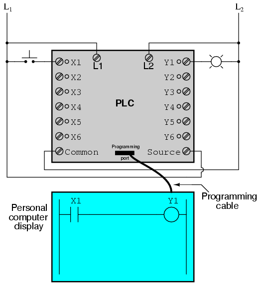
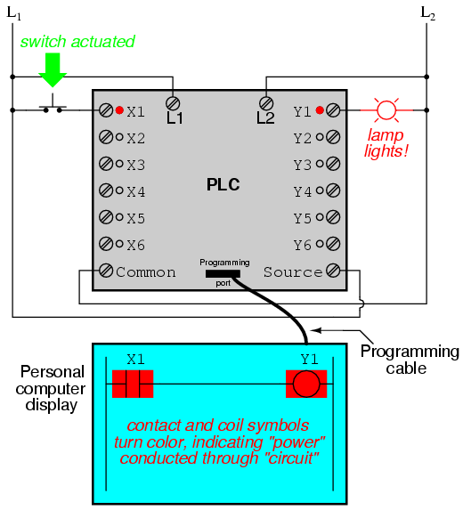
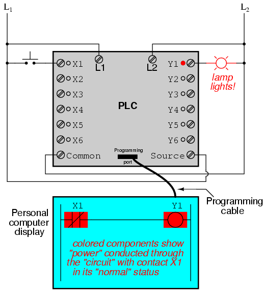
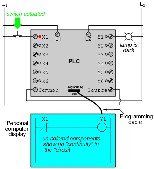
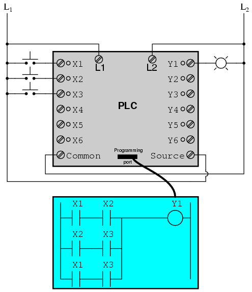
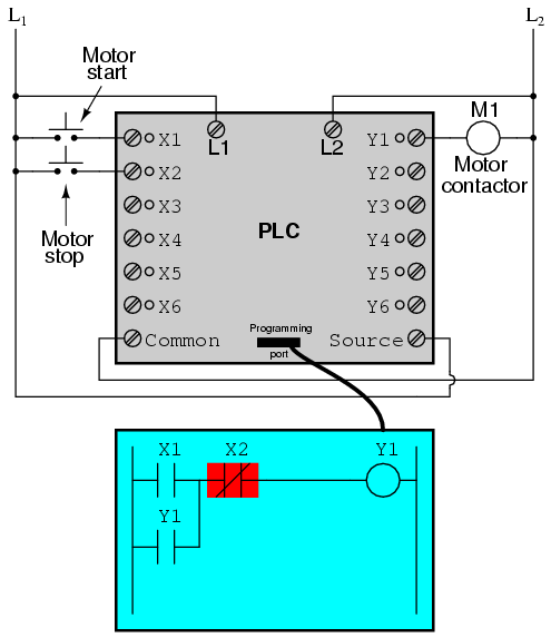
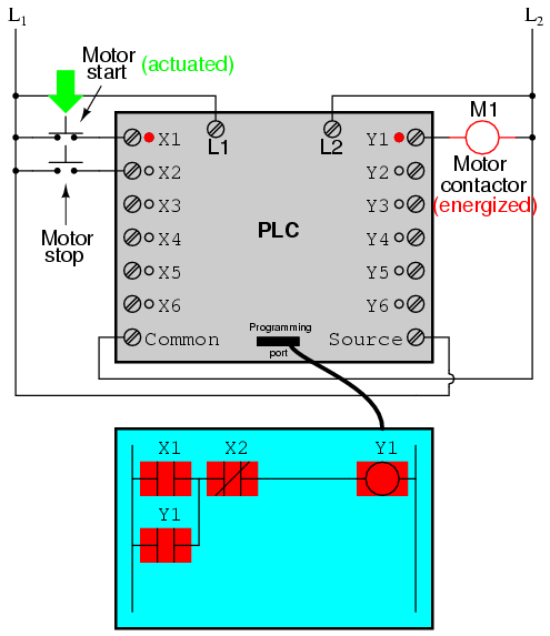
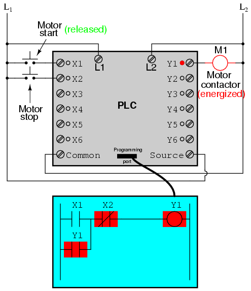

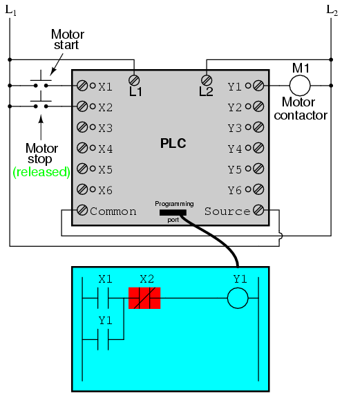
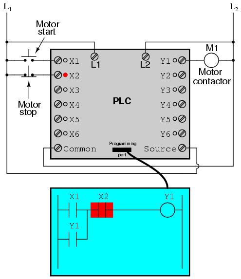
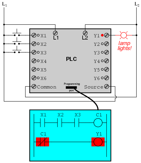
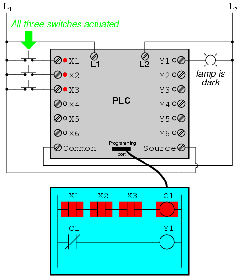
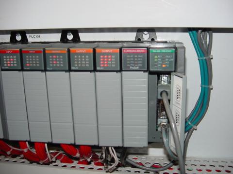


 You cannot mount the PLC vertically, upside down, or on a flat horizontal surface. Provide a minimum clearance of 40mm between the PLC and all sides of the enclosure.
  The end bracket helps keep the PLC from sliding horizontally along the rail, reducing the possibility of accidentally pulling the wiring loose.
 In some instances, it may be desirable to remove the terminal block for easy wiring. The terminal block is designed for easy removal with just a small screwdriver. Minimum wire sizes, color coding, and general safety practices should comply with appropriate electrical codes and standards for your area. Each terminal connection of the PLC can accept one 16 AWG wire or two 18 AWG size wire. Avoid running DC wiring close to AC wiring where possible.